
Installation guide of Pressure Sensors
Installation guide of Pressure Sensors
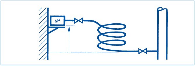
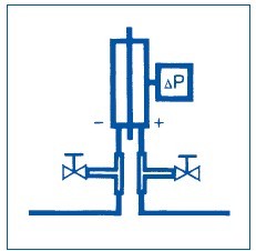 Pressure tubes must be provided with an isola table T-fitting near the device head for test purposes.
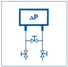 To prevent overload on one side when making adjustments, the connection must always be fitted with an isolating bypass.
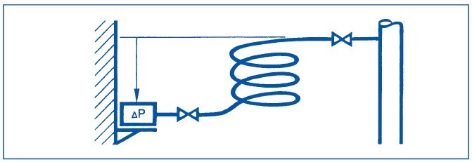
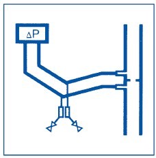 Where there is a risk of condensation, the differential pressure tube must be installed at a gradient of 1:30 and fitted with a drain mechanism. The drainage point must be lower than the de -
vice head and sensing point. Protect from frost
and avoid U-shapes.
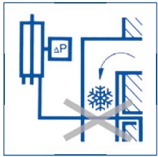 Pressure tubes containing circulating air must not be introduced into the open air or routed through cold rooms or ducts.
This prevents the risk of condensate freezing in the tubes (e.g. with pneumatic venting sensors).
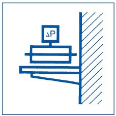 Mount on a vibration-free surface.
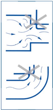
 The pressure-tapping point must not be located in turbulent air. Ensure sufficiently long settlingzones upstream and downstream of the tapping point.
A settling-zone consists of a straight section of pipe or duct, with no obstructions.
Pressure Air
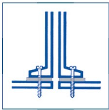 The measuring tip is screwed or glued to the duct wall.
Seal to protect from external air. Remove any swarf from the inside of the duct.
 Important:Protruding fixing screws will impair correct measurement.
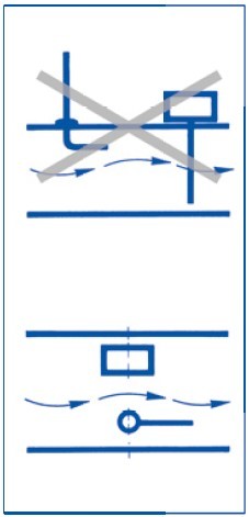
 Avoid using tips which protrude into the duct for static pressure measurements.
 Probes are used to measure static pressure in the duct. Must be installed parallel to the flow and either with the flow or against it.
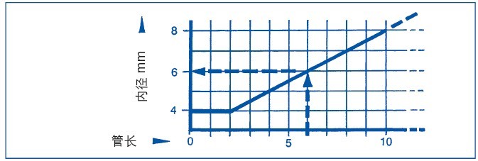
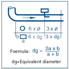
Sizing the pressure tubes (“measuring tubes”)
for air and gases: Keep the tube as short as possible.
An internal diameter of 4 mm is sufficient for pressure tubes of up to two metres in length. For longer pressure tubes, the internal diameter should be as indicated in the diagram.
(Example: A pressure tube of 6 m requires an internal diameter of 6 mm.)
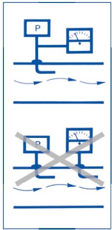 Connect the sensor and measuring instrument to the same point.
 The tapping point must not be located where it will be affected by obstructions to the flow.
 Where more than one sensor is used, the sensors should be installed on the same plane in the flow, and not in a position where one device will obstruct the air flow to the other.
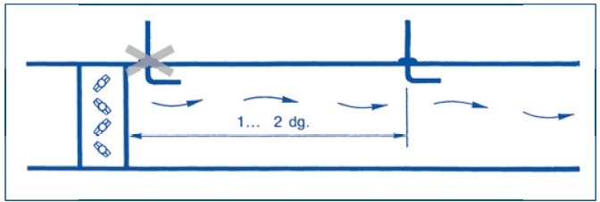
dg = Equivalent diameter, page 45 Leave sufficient clearance downstream of any obstacles.
Pressure · Air
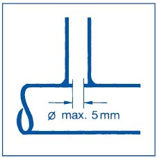 Pressure tapping point:Sensing hole: diameter 5 mm, drilled and deburred.
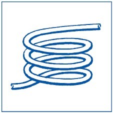 Use a damping coil to avoid transferring vibra -tions. Bend a 1 m long copper pipe, 4…6 mm in diameter, into a spiral with loops with a diameter of 15 cm.
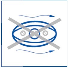
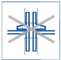
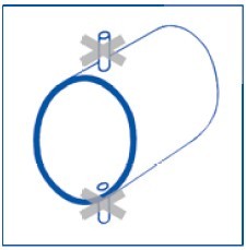
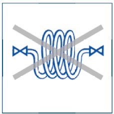 Wrong:Air bubbles and condensate remain trapped.
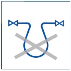 Wrong:Condensate cannot be drained.
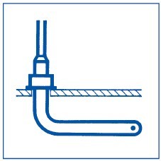
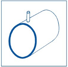
Installation in conjunction with liquids:
Always install the pressure sensor in a location which is lower than the sensing point.
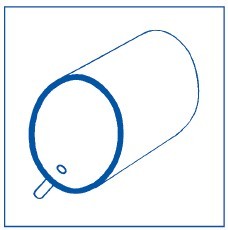
Installation in conjunction with vapours/gases
Always install the pressure sensor in a location which is higher than the sensing point.
 Pressure measurement in conjunction with liquids:Do not measure at the top of the pipe (trapped air or air bubbles) or at the bottom (dirt).
 The correct location for a sensing point is at the side.
 Condensing gases:Measure at the top to prevent condensate fromentering the pressure tube.
- Pre:None
- Next:Installation guide of Duct Hum 2016/5/10